In modern industry, wear, corrosion, and fatigue failure of critical metal components are common problems. Traditional repair methods often come with the risk of high heat input, part deformation, or insufficient bond strength, while replacing entire high-value components incurs high costs and significant downtime. Is there a technology that can precisely repair components while strengthening the surface, or even directly create complex structures unattainable with traditional processes? Laser cladding (LC) technology offers an effective solution to these challenges. It can in-situ deposit one or more layers of high-performance alloys without damaging the component itself, achieving metallurgical bonding at the atomic level.
This article will analyze the following aspects:
1. LC Technology Principles and Core Advantages. How does laser cladding (LC) achieve the two key characteristics of high bond strength and low thermal deformation through its unique physical mechanism?
2. Analysis of the Complete LC Process. How do the laser beam, metal powder, and substrate interact in an extremely short time to form a dynamic and stable micro-molten pool?
3. Analysis of Key Process Parameters and Their Influencing Mechanisms. Why are laser power, scanning speed, and powder feed rate the three key factors in process control? How do they jointly determine the geometry, dilution rate, and final performance of the cladding layer?
4. Comparative analysis of LC with other surface engineering technologies. Compared with plasma arc welding (PTA), thermal spraying, and hard chrome plating, what are the unique advantages and limitations of LC in different industrial scenarios? How should technology selection be made in engineering applications?
LC Technology Principles and Core Advantages
I. Working Principle
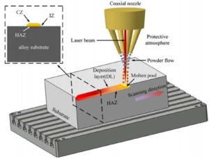
Laser cladding (LC) is an advanced surface enhancement and additive manufacturing technology. Its core principles can be broken down into the following steps:
1. Precision Heating: A high-energy-density laser beam is precisely applied to a specific area of the workpiece.
2. Molten Pool Formation: The laser beam’s energy instantly melts the surface metal of the part, forming a tiny, flowing pool of molten metal, known as the melt pool.
3. Material Delivery: Simultaneously, a pre-set amount of metal powder or wire is precisely fed into the melt pool through the nozzle of the laser cladding head.
4. Melting and Mixing: The material entering the melt pool rapidly melts under the continuous action of the laser and thoroughly mixes with the molten surface metal of the base material.
5. Rapid Solidification: As the laser beam moves along the set path, the melt pool behind it loses its energy source. Heat dissipation from the workpiece causes the melt pool to cool and solidify at an extremely high rate. 6. New Layer Formation: This process ultimately forms a new alloy layer on the workpiece surface that is completely integrated with the base material. The key to the entire process is the metallurgical bond between the newly formed coating and the substrate. This means their atoms have diffused and fused together, creating a bond that rivals the strength of the base metal itself. This fundamentally eliminates the risk of the coating flaking or delaminating during use, a fundamental advantage of LC over many other coating technologies.
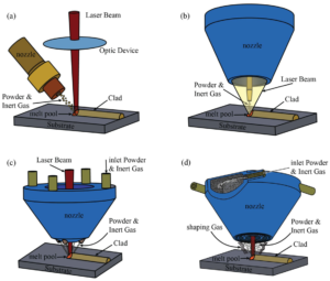
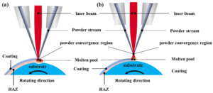
*LC process diagram
* Powder feeding method: a) lateral powder feeding; b) light-encapsulated powder – ring laser powder feeding; c) powder-encapsulated light – discrete multi-beam coaxial powder feeding; d) powder-encapsulated light – continuous ring coaxial powder feeding
LC technology has three major application areas: repair and remanufacturing:
1. Repairing high-value, critical components that have failed due to wear, corrosion, or fatigue, such as aircraft engine turbine blades and large molds, to restore their dimensions and performance.
2. Surface enhancement and modification: A coating with specialized properties such as high hardness, wear resistance, corrosion resistance, or high-temperature resistance is deposited onto a relatively inexpensive substrate. This significantly improves the surface performance and service life without altering the mechanical properties of the underlying part.
3. Additive manufacturing: Complex metal parts are generated directly from 3D CAD models by depositing materials layer by layer, or new functional structures are fabricated on existing parts.
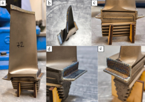
*Rotor blade repair
2. Molten Pool Flow and Solidification
Laser cladding is far more than simply piling up materials. The complex interactions within the molten pool and the subsequent solidification process determine the final quality of the cladding layer.
Internal Flow in the Molten Pool
Under laser irradiation, temperature variations on the surface of the molten pool create surface tension differences, inducing a violent agitation known as “Marangoni convection.” This internal agitation allows newly added alloying elements to mix very evenly with the matrix elements, but it can also affect the stability of the molten pool.
Rapid Solidification
LC cooling rates can reach as high as 10³ K/s to 10⁶ K/s. This non-equilibrium process of rapid cooling and heating is the fundamental reason for high-performance cladding layers. It provides two major benefits:
1. Microstructural refinement: The extremely rapid cooling rate prevents crystal growth during solidification. As a result, LC cladding layers are typically composed of very fine grains (such as dendrites and cellular crystals). According to the classic Hall-Page theory, the finer the grain size, the higher the strength and hardness.
2. Non-equilibrium phase formation: Under rapid cooling, the solid metal can contain more alloying elements than normal, forming a supersaturated solid solution. This can even lead to the formation of special metastable phases or amorphous structures that do not exist under slow cooling. These unique microstructures often impart higher strength, hardness, and corrosion resistance to the material.
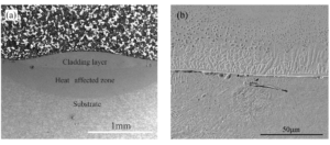
*Metallurgical bonding of cladding layer: a) cross-sectional morphology; b) bottom structure
3. Core Technology Advantages
Low heat input, high bond strength, and flexible material selection.
LC’s unique physical process offers the following key advantages:
① Low heat input and small heat-affected zone (HAZ)
The laser energy is highly concentrated within a small spot, resulting in an extremely short exposure time. Although the melt pool temperature is high, the total heat transferred to the entire workpiece is extremely low. This results in a very narrow heat-affected zone (HAZ), the area where the workpiece undergoes structural and property changes due to heat.
The most direct benefit is minimal thermal deformation or warping of the workpiece, which is crucial for repairing precision components and strengthening thin-walled structures.
② Low Dilution
Dilution refers to the percentage of the cladding layer’s components that originate from the melted base material. Because LC precisely controls energy input, melting only a very thin surface layer of the base material can be achieved. Consequently, the degree of intermixing between the cladding layer and the base material can be kept low, typically less than 10%, compared to over 20% with conventional overlay welding.
This low dilution ensures that the cladding layer retains its designed chemical composition to the greatest extent possible, ensuring its intended properties, such as wear and corrosion resistance, are fully realized.
③ High Density and High Bond Strength
As mentioned above, LC is a metallurgical bond with extremely high strength. With appropriate process protection, the cladding layer achieves an extremely dense structure, virtually free of pores and inclusions, and a density exceeding 99.9%.
④ Material and Process Flexibility
LC is applicable to virtually all weldable metals, including steel, high-temperature alloys, and titanium alloys. More importantly, a multi-channel powder feeding system allows for real-time mixing of different powders to create functionally graded materials with transitions from one material to another, providing greater flexibility in material design. At the same time, LC can be easily integrated with CNC machine tools or robots to achieve automated production, ensuring process stability and repeatability.
4. Key Terms
LMD, DED, and LC are often used interchangeably. Here’s a breakdown:
1. Laser Metal Deposition (LMD): This is a commonly used term internationally, accurately describing the core of the technology: metal deposition using a laser.
2. Direct Energy Deposition (DED): This is a broader term for additive manufacturing techniques that use focused energy to directly melt and deposit material.
3. Laser Cladding (LC): This term focuses more on the technology’s applications in surface coating and repair, emphasizing the concept of forming a coating. In this article, we primarily use the term laser cladding (LC) because it focuses on surface coating and repair.
LC complete process
The laser cladding process doesn’t end with the cladding itself; it’s a systematic process that encompasses three closely linked stages: pre-treatment, cladding, and post-treatment.
1. Pre-treatment
This is essential for ensuring a good bond and avoiding defects.
Surface Cleaning and Preparation
1. Surface contaminants such as oil, rust, and scale on the workpiece will decompose and vaporize under the laser’s action, easily forming pores and inclusions in the cladding layer.
Chemical Cleaning: Wipe with a solvent such as alcohol to remove oil.
2. Mechanical Treatment: Remove oxide layers and rust through sandblasting, grinding, and other methods. For repaired parts, fatigue layers and cracks must be completely removed.
Preheating Process
Preheating is a crucial step for heat-sensitive and crack-prone materials such as high-carbon steel, tool steel, and cast iron.
Action 1: Reduces temperature gradients. Preheating significantly minimizes the significant temperature difference between the high-temperature molten pool and the room-temperature substrate. Thermal stress is proportional to the temperature gradient, so preheating can significantly reduce the thermal stress generated during the cooling process, thereby reducing the risk of cracking.
Action 2: Slows cooling. A preheated substrate dissipates heat more slowly, effectively slowing the cooling rate of the molten pool. This helps prevent the formation of hard and brittle martensite in the steel and improves its toughness.
The actual preheating temperature depends on the chemical composition, thickness, and shape of the substrate.
Powder Drying: Metal powders may absorb moisture from the air, which can cause porosity and hydrogen-induced cracking in the cladding layer. Therefore, to eliminate these risks, thorough drying of the powder before cladding is a standard practice to ensure a dense, defect-free cladding layer.
2. Cladding Stage
Material Delivery System
Powder feeding: This is the most popular method. Metal powder is fed into the molten pool through a nozzle using an inert gas.
Coaxial powder feeding: Powder is ejected from a nozzle surrounding the laser beam and converges at a focal point. Its advantage is that it is independent of the processing direction and is suitable for cladding complex structures.
Paraxial powder feeding: Powder is ejected from a nozzle lateral to the laser beam. This simple structure exhibits distinct directionality.
Wire feeding: A disc-shaped metal wire is used as the filler material.
Advantages: Nearly 100% material utilization, no powder splashing, and a cleaner process. Wire is generally less expensive than spherical powders of the same composition.
Disadvantages: Higher requirements for molten pool stability, a narrower process window, and less adaptability to complex shapes than powder feeding.
Melt pool control and protection
Laser-material coupling: To achieve efficient and stable cladding, the focal point of the laser beam and the convergence point of the powder beam (or the end point of the wire) must coincide on the workpiece surface. Shielding gas: The molten pool and heat-affected zone at high temperatures are very susceptible to reaction with oxygen and nitrogen in the air, producing oxides and nitrides, which can lead to defects such as inclusions and pores. Therefore, an inert gas (usually high-purity argon) must be used to effectively protect the cladding area and isolate it from the air.
3. Post-Processing Stage
After cladding is complete, post-processing is typically required to eliminate residual stresses and achieve final dimensional and surface requirements.
Heat Treatment Process
Stress Relief Annealing: The extreme temperature gradients and rapid cooling during LC inevitably introduce significant residual stresses, primarily tensile, in the cladding layer and the adjacent substrate. When these stresses exceed the yield strength of the material, deformation or cracking can result. Therefore, post-cladding heat treatment is essential for parts with complex structures or high precision requirements. Typically, the entire workpiece is heated to an appropriate temperature below the phase transition point, held at that temperature for a period of time, and then slowly cooled. This releases most of the internal stress through atomic diffusion and microplastic deformation.
Performance Control Heat Treatment: In addition to stress relief, quenching, tempering, solution treatment, or aging treatments can be performed as needed to further optimize the mechanical properties of the cladding layer, such as hardness and toughness.
Surface Finishing
LC is a near-net-shape technology that offers surface quality and dimensional accuracy far superior to traditional cladding. However, slight waviness and contour errors are often present, making it difficult to directly meet the demands of precision applications. Therefore, most LC parts require final machining, such as turning, milling or grinding, to remove excess allowance to achieve the final size and surface finish required by the drawing.
Key process parameters and influencing mechanisms
The final quality of the cladding layer is determined by a series of complex process parameters, the essence of which is the understanding of energy matching: the energy input per unit time needs to be precisely matched with the input material and the heat required for melting.
1. Core Input Parameters
① Laser Power (P): The most direct energy input parameter. Higher power increases the temperature, depth, and width of the melt pool, melting more of the base material and increasing the dilution rate. Too low power may result in insufficient powder melting, resulting in unfused defects. Too high power can overmelt the base material, leading to excessive dilution and even alloy burnout, resulting in microstructure coarsening.
② Spot Size (d): Determines the energy distribution density on the workpiece surface. At constant power, a smaller spot size results in higher power density (W/cm²), more concentrated energy, increased penetration depth, but reduced weld width. The reverse is also true.
Spot size is a key parameter for controlling the penetration depth/width ratio and dilution rate.
③ Scanning speed (v): The speed at which the laser beam moves across the workpiece surface. The faster the speed, the shorter the laser’s exposure time at a given point, resulting in less energy per unit area. Therefore, increasing the speed reduces penetration depth, width, and cladding layer height, and the dilution rate also decreases. Too fast a speed prevents the powder from melting quickly; too slow a speed equates to excessive energy input. Furthermore, the scanning speed directly determines the cooling rate, thus affecting the degree of grain refinement.
④ Powder/wire feed rate (m): The mass of material delivered per unit time. With the same energy input, increasing the powder feed rate means more material is deposited per unit length, resulting in an increase in cladding layer height and width. However, if the powder feed rate is too high and the energy is insufficient, incomplete powder melting can occur, leading to defects such as powder inclusions and incomplete fusion.
⑤ Overlap ratio: When performing multiple overlapping passes, the percentage of the width of the previous pass that is covered by the subsequent pass. The overlap ratio directly affects the smoothness of the entire cladding surface. If the overlap ratio is too low, grooves will form between the passes; if it is too high, material waste and excessive heat accumulation will occur.
An appropriate overlap ratio (typically 30%-50%) not only ensures a smooth surface, but also acts as an in-situ “tempering” process by applying heat from the subsequent pass to the previous one, helping to adjust the microstructure and reduce stress.
2. Interactions between Parameters
These parameters do not act independently but are coupled to each other.
For example, simply increasing power will increase the dilution rate, but simultaneously increasing the scan speed proportionally can significantly improve production efficiency while maintaining a similar dilution rate.
To better quantify this combined effect, energy density is often used in engineering assessments.
Linear energy density (J/mm) = P / v
Area energy density (J/mm²) = P / (v * d)
These parameters link several key variables to reflect the energy input level. Within a certain range, many properties of the cladding layer are strongly correlated with energy density. Different material combinations have different process windows, and only when the parameter combination falls within this window can a high-quality cladding layer be achieved.
3. The Comprehensive Impact of Parameters on Cladding Layer Quality
Geometry and Dilution Rate Control
An ideal cladding layer should have a smooth surface, a good wetting angle, and a minimal dilution rate, such as <5%. A strategy typically employed is to match a high scanning speed with a laser power that ensures sufficient powder melting.
Microstructure Evolution: Process parameters determine the final microstructure by altering the “thermal history” of the melt pool.
Cooling Rate: This is primarily determined by the scanning speed; faster speeds result in faster cooling and finer grains.
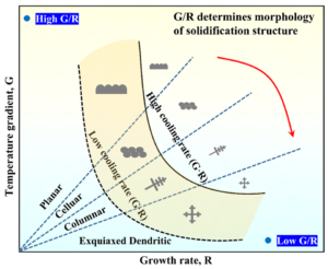
Temperature Gradient (G) and Solidification Rate (R): These two parameters jointly determine the crystal growth morphology. By manipulating the power (which influences G) and speed (which influences R), the solidification structure can be controlled to transition from columnar to equiaxed crystals.
*Effects of temperature gradient (G) and solidification rate (R) on dendrite morphology
Mechanical Property Control
Hardness: This is primarily determined by the chemical composition and the degree of microstructural refinement. Within the process window, faster cooling rates generally result in finer grains, leading to higher hardness. However, excessive energy input can lead to grain coarsening and increased dilution, which in turn reduces hardness.
Defect Formation and Crack Suppression: The root cause is excessive residual tensile stress. Excessive energy input, rapid cooling rates, inappropriate scanning paths, and significant differences in thermal expansion coefficients between materials are all major contributors to cracking. Suppression measures include preheating, optimizing energy input, adopting a zoned/segmented scanning strategy, and selecting a suitable transition layer material.
Porosity: Porosity is primarily caused by: 1) shielding gas being drawn into the melt pool; 2) the powder itself being hollow or having air and moisture adsorbed on its surface; and 3) insufficient or impure shielding gas flow, leading to melt pool oxidation. Suppression measures include optimizing the powder feed gas flow rate, ensuring dry and high-quality powder, and providing sufficient and stable gas shielding.
LC and other surface engineering technologies
Choosing a technology isn’t about the best, but the most suitable. First, determine the core pain points of the application scenario: part precision and deformation, coating bonding strength, or cost and efficiency? This allows you to make the right decision.
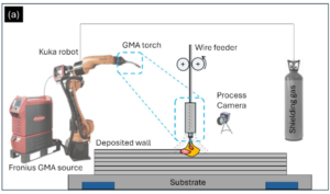
* Conventional arc cladding (GMA)
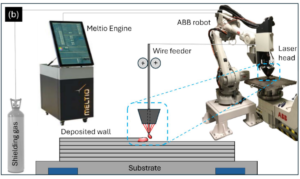
*Laser Cladding (LC)
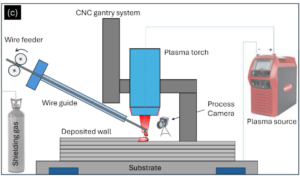
*Plasma Arc Welding (PTA)
1. LC vs. Plasma Arc Welding (PTA)
PTA is LC’s most direct competitor in the field of high-performance coatings.
Core Differences
Heat Source: LC uses an extremely high-energy-density laser beam, while PTA uses a relatively dispersed plasma arc. This results in significantly lower total heat input for LC than for PTA, resulting in a narrower heat-affected zone and less thermal deformation and damage to the substrate. LC offers a clear advantage for precision, thin-walled, or heat-sensitive components.
Dilution Rate and Coating Purity: LC offers more precise energy control, enabling very low dilution rates, such as <5%, while PTA typically operates at 10%-20%. This lower dilution rate means that LC coatings more completely retain their designed alloy composition, resulting in superior performance.
Deposition Efficiency and Cost: Traditionally, PTA, due to its higher energy and powder feed rate, has been more efficient and cost-effective for large-area, thick-coating applications.
However, with the rapid adoption of high-power fiber lasers in recent years, LC’s deposition efficiency has significantly improved, and the gap is narrowing.
Precision and Flexibility: LC’s laser beam focus can be very small, enabling extremely high positioning accuracy. When processing complex geometries such as fine structures, thin edges, and narrow grooves, LC’s flexibility and precision far exceed PTA.
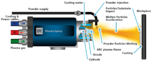
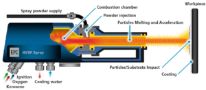
2. LC vs. Thermal Spray (HVOF, Plasma Spray)
The fundamental difference between the two is the fundamental bonding mechanism. LC is a metallurgical bond with extremely high bond strength. Thermal spray is a mechanical bond, where coating particles impact and embed onto the substrate surface at high speed. This bond relies on physical embedding and van der Waals forces, resulting in significantly lower strength than metallurgical bonding and the risk of spalling under impact or thermal cycling loads.
Coating Density and Porosity
LC cladding is formed by complete melting and solidification, resulting in a completely dense structure and extremely low porosity. Thermal spray coatings, on the other hand, are composed of countless deformed, stacked particles. Tiny pores, ranging from 1% to 10%, inevitably exist between the particles. These pores can serve as penetration channels for corrosive media.
Heat Input and Substrate Impact
During the thermal spray process, although the particle temperature is very high, the total heat transferred to the substrate is minimal, and the overall substrate temperature rise can be controlled below 150°C. Therefore, thermal spray has virtually no impact on the substrate’s structure and properties, a unique advantage when processing heat-sensitive materials. LC can produce coatings ranging from tens of microns to several millimeters or even thicker. Thermal spraying is typically used for thinner coatings (less than 1 mm). Coatings that are too thick are prone to cracking due to internal stress. However, thermal spraying offers a wider range of materials, allowing it to spray almost any material that can melt or soften without decomposing (including metals, ceramics, and plastics).
* Schematic diagram of plasma spraying
*High Velocity Oxygen Fuel (HVOF)
3. LC vs. Traditional Arc Welding and Hard Chromium Plating
vs. Traditional Arc Welding (TIG, MIG): LC can be considered an upgraded version of traditional overlay welding technology in terms of precision and performance, offering significant advantages in energy density, precision, heat input control, heat-affected zone width, and workpiece deformation.
vs. Hard Chromium Plating: Hard chromium plating, due to the presence of highly toxic and carcinogenic hexavalent chromium in its wastewater, is subject to increasingly stringent environmental regulations in the EU and globally. LC, as a clean, pollution-free dry process, is an ideal alternative to hard chromium plating. In terms of performance, LC coatings (such as nickel- and cobalt-based alloys) not only rival or even surpass hard chromium coatings in hardness and wear resistance, but more importantly, their metallurgical bonding avoids the microcracks common in hard chromium coatings, resulting in superior toughness, fatigue resistance, and corrosion resistance, resulting in a longer service life. The emergence of high-speed laser cladding (HS-LMD) technology has successfully addressed the low efficiency and high cost of traditional LC, making it a formidable alternative to hard chromium plating.
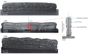
*Deposition samples prepared by different processes and their characterization: PTA, LMD, GMA
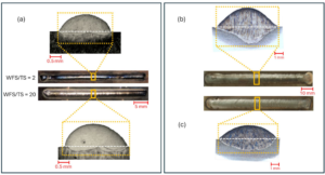
*Single-channel cross-section comparison: a) LMD; b) GMA; c) PTA
Frontier Progress & Core Challenges
1. Cutting-Edge Technology
High-Speed Laser Deposition (HS-LMD/EHLA)
The core innovation of HS-LMD lies in the fact that the powder is fully preheated by the laser to near its melting point while in flight, before reaching the workpiece surface. This allows for melting and fusion with minimal additional energy, resulting in groundbreaking benefits:
Extremely high speeds: Deposition speeds can reach hundreds of meters per minute.
Thinner coatings: Coatings as thin as 25-250μm can be consistently produced.
Lower heat input: The HAZ can be narrowed down to the micron level.
This makes HS-LMD an ideal alternative to hard chrome plating for the efficient reinforcement of large rotating components such as hydraulic rods and rollers.
*a) Conventional laser cladding; b) High-speed laser cladding
Wire Laser Deposition (Wire-LMD)
By introducing “hot wire” technology—preheating the wire material with a resistance resistor before feeding—the energy required for laser melting can be significantly reduced, significantly increasing the deposition rate and further amplifying the efficiency and cost advantages of wire-LMD.
Specialized Wavelength Laser Cladding
For highly reflective materials such as copper and aluminum, traditional infrared lasers have low absorption rates, resulting in unstable processes. Cladding with shorter wavelength green lasers (approximately 515-532 nm) is a promising method. Copper and aluminum have much higher absorption rates than infrared light, enabling stable, high-quality cladding with lower power.
2. Core Challenges
Residual stress and crack control: This remains a primary challenge for LC technology, especially when processing large, complex, or dissimilar material combinations. Managing stress is crucial to ensuring products do not crack or deform.
New Material Development: Currently, most materials used in LC were developed for conventional welding or spray coating. Designing and developing new alloy powders or wires specifically tailored to LC’s unique rapid solidification characteristics is an ongoing effort to expand its application areas.
Conclusion & Selection
Conclusion
1. Technical Essence: LC is an advanced technology based on the principles of localized heating using high-energy lasers and rapid material solidification. Its core advantages lie in strong metallurgical bonding, excellent coating properties, and minimal thermal damage and deformation to the substrate.
2. Process Core: The key to LC’s success lies in the precise and coordinated control of parameters such as laser power, scanning speed, and powder feed rate. Its essence lies in achieving a dynamic balance between energy input and mass input.
3. Technical Positioning: Compared to traditional technologies, LC offers significant advantages in precision, minimal damage, bond strength, and environmental friendliness.
Selection
1. Shift from technology comparison to a problem-oriented approach. When selecting a technology, avoid falling into a general comparison of LC, PTA, and thermal spray. The starting point for decision-making should be a precise assessment of the core pain points of the application scenario: Is thermal deformation the primary issue? Is it insufficient bond strength? Or is it a cost-effectiveness bottleneck? If the core issue is precision and minimal damage, LC is the obvious choice; if the core requirement is large-scale, high-efficiency coating with little sensitivity to deformation, PTA may be more economical. A problem-oriented approach ensures that technology truly meets the needs.
2. Future-oriented. Take the replacement of hard chrome plating as an example: Due to the highly toxic and carcinogenic hexavalent chromium in its wastewater, hard chrome plating faces increasingly stringent environmental regulations in the EU and globally. The trend of replacement is becoming increasingly clear, and it is only a matter of time before the domestic industry fully follows suit. In this application context, the significance of high-speed laser cladding goes far beyond efficiency improvements. It represents a low-cost, high-performance, and environmentally friendly solution. It offers the opportunity to tap into this huge existing market and, through its differentiated advantages, gradually promote industry replacement and upgrading.