01
This article explores the core principles of laser scanning galvanometers and the underlying physics and control logic:
1.How is the motion of the optical beam driven? What irreconcilable conflict exists between the motor’s inertia and the optical aperture?
2.What is the gap between command and execution? Does the system simply passively chase the target (tracking error) or can it proactively predict the path (feedforward control)?
3.How can system stability be guaranteed with microsecond response times? Where do jitter and thermal drift originate?
4.When the galvanometer and motion platform work together, how are motion commands intelligently decomposed and dispatched? How can stitching errors be fundamentally eliminated?
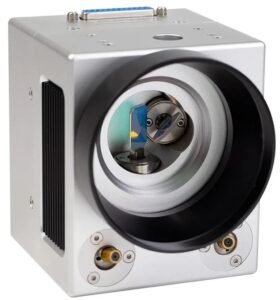
*A certain SG7210 model scanning galvanometer
02 Galvanometer Scanning Basics: How Does It Work?
To understand a complex system, we must first return to its core. This section will focus on the basic physics and concepts related to scanning galvanometer technology.
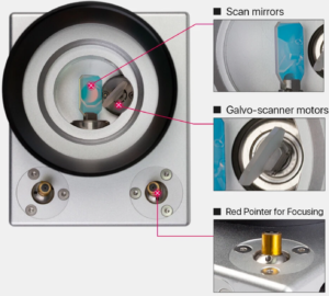
* Scanning mirror components
1. It All Starts with Deflection
The essence of laser scanning is the precise and controllable deflection of a laser beam. Without deflection, the laser emits a static beam of light, limiting its application scenarios. Scanning technology transforms this static beam of light into a dynamic one, allowing it to be directed anywhere, greatly expanding the application of lasers in machining, marking, imaging, and other fields.
To achieve deflection, the industry has developed a variety of technologies, each with its own advantages and disadvantages:
1. Rotating polygonal mirrors: These are extremely fast, but typically only perform periodic, one-dimensional scanning, similar to roller printing.
2. Acousto-optic/electro-optic deflectors: These offer fast response times (nanoseconds), but are very limited in deflection angle and beam diameter.
3. Scanning galvanometers: These offer exceptional speed, high precision, and flexible vector addressing capabilities, enabling them to quickly and precisely direct the laser beam to any position within the work plane according to computer instructions.
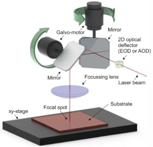
*Laser scanner: Scanning galvanometer + electro-optical/acousto-optical deflector (EOD/AOD)
2. Oscillating Motor
Fundamentally, a galvanometer scanner is a specialized, high-precision oscillating motor. Its operating principle is based on a classic law of physics: the Lorentz force. The principle is: When a current-carrying coil is placed in the magnetic field generated by a permanent magnet, it experiences a torque, causing it to rotate. The magnitude of this torque is proportional to the current flowing through the coil. The principle is identical to that of a galvanometer. In a galvanometer, current drives the coil, which in turn deflects a pointer. The angle of the pointer’s deflection directly reflects the magnitude of the current. In a galvanometer scanner, the pointer is replaced with a highly reflective lens. The drive current controls the lens’s deflection angle. Through a sophisticated servo control system, the galvanometer does not rotate continuously, but rather remains precisely stabilized at a target angle determined by the input signal. The driver board converts the input voltage signal into a precise drive current, thereby achieving precise control of the lens’s angle.
3. Constructing the Scanning Plane
A typical two-dimensional (2D) scanner consists of two galvanometer scanning mirrors, their rotation axes mounted perpendicular to each other.
1. The laser beam first strikes the first mirror (usually defined as the X-axis).
2. After reflection from the X-mirror, the beam strikes the second mirror (the Y-axis). By independently controlling the deflection angles of these two mirrors using a computer, the system can precisely direct the laser spot to any (X,Y) coordinate within the 2D working plane. This vector-based random addressing capability is the core advantage of galvanometer scanning mirrors over raster scanning systems like polygon mirrors.
4. Jump & Marking
The scanning galvanometer movement can be divided into two basic modes, determined by the laser’s on/off state and precisely synchronized by the control system.
1. Jump Movement: This is repositioning with the laser off. During this period, no processing is performed, so the galvanometer moves to the starting point of the next processing task at its highest achievable speed and acceleration.
2. Marking Movement: This is processing with the laser on. In this mode, the galvanometer’s movement speed is strictly controlled to meet specific process requirements.
This analysis has touched upon a core contradiction in galvanometer scanning mirror design:
1. The pursuit of speed: To achieve extremely high acceleration, the motor must generate strong torque; at the same time, the rotor (including the lens, shaft, etc.) must have as low a moment of inertia as possible. The lower the inertia, the faster the start and stop.
2. The pursuit of power and quality: To fully accommodate the laser beam and prevent energy clipping by the lens edges, resulting in energy loss or beam quality degradation, the lens size (clear aperture) must be sufficiently large. This is especially important in high-power applications.
These two requirements are in direct conflict: a larger lens inevitably results in greater mass and moment of inertia. This explains why there is no universal galvanometer scanning mirror, and why the market offers a wide range of apertures, from 3mm to 50mm and even larger.
1. Small-aperture galvanometers: Low inertia and extremely high speed make them suitable for applications with small beam spots and high dynamics, such as biomedical imaging. 2. Large-aperture galvanometers: They have large inertia and slower speeds, but can withstand high-power lasers and are primarily used in laser welding, cutting, and 3D printing. Therefore, the choice of galvanometer is always a trade-off and optimization between speed and power handling capabilities for a specific application.
03 A complete scanning galvanometer system
A high-performance scanning system is more than just a single galvanometer; it’s a sophisticated system comprised of multiple key components working in concert.
System Architecture: A typical system workflow is as follows:
1. A laser source generates a laser beam.
2. It passes through an upstream beam expander for collimation and shaping.
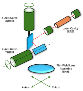
3. The shaped beam enters the scan head and is deflected by the X/Y galvanometer lenses.
3. The deflected beam passes through an F-Theta field lens, where it is focused and linearized.
5. Finally, the focused beam spot is applied to the workpiece surface.
The entire process is precisely controlled by a control card and software, forming a complete closed loop from digital instructions to physical processing.
*Schematic diagram of scanning galvanometer system
2. Galvanometer Motor
The galvanometer motor directly determines the system’s dynamic performance and consists primarily of three components:
Stator and Rotor:
1. Moving Magnet: The magnets are part of the rotor, and the coils are fixed to the stator. This is the mainstream choice for current high-performance systems. Its advantages include a simple rotor structure and low inertia, enabling the system to achieve a higher resonant frequency and faster response time.
2. Moving Coil: The coils are part of the rotor, and the magnets are fixed. While this design offers higher torque efficiency, the volume and mass of the coils result in a larger rotor inertia, limiting its maximum response speed.
Bearings: These are critical to ensuring the long-term stable and reliable operation of the motor. High-quality, axially preloaded precision ball bearings are typically used to ensure zero backlash, high rigidity, low friction, and an extremely long rotor life.
3. Scanning Lenses
Lens performance directly impacts the system’s optical quality and power handling capability.
Aperture: The effective clearing diameter of the lens, which determines the maximum beam diameter the system can handle.
Substrate Materials:
1. Silicon (Si): With excellent thermal conductivity and high rigidity, it is a common choice for medium- and high-power infrared lasers (such as CO₂ and fiber lasers).
2. Fused Silica: With an extremely low coefficient of thermal expansion, it exhibits minimal deformation with temperature changes. Therefore, it is the preferred material for UV and ultrafast laser applications to avoid focus drift caused by thermal lensing.
Coating: The lens surface is coated with multiple layers of dielectric films to achieve extremely high reflectivity at specific wavelengths, typically >99.5%.
4. F-Theta Lens
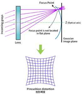
Without an F-Theta lens, scanning systems face two critical issues:
1. Field curvature: A standard focusing lens focuses the beam onto a curved surface rather than a flat surface.
2. Nonlinearity and pincushion distortion: On a plane, the beam spot’s displacement y’ is proportional to the tangent of the scanning angle θ, i.e., y’ = f·tan(θ). This means that when the lens scans at a constant angular velocity, the beam spot’s movement speed on the working plane will vary (faster at the edges, slower at the center). This not only results in uneven energy density but also produces pincushion distortion, where a square is scanned as a pillow.
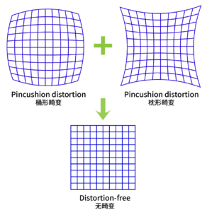
Solution: F-Theta Lens
The F-Theta lens (also known as a field lens) is a specially designed multi-lens assembly. It is precisely engineered to introduce a certain amount of barrel distortion, which counteracts the pincushion distortion and nonlinear effects inherent in the scanning process. Ultimately, the on-plane displacement of the beam spot becomes approximately linear with the scanning angle (y’ ≈ f·θ).
The core functions are summarized as follows:
1. Linearized Scanning: Ensures that the beam spot moves at a constant speed as the galvanometer rotates.
2. Flat-Field Focusing: Ensures that the beam spot remains focused throughout the entire scanning field.
3. Uniform Spot Size: Provides uniform energy density throughout the entire scanning field.
*Without F-Theta lens
*With F-Theta lens: introduces barrel distortion
5. Beam Expander
Before the laser enters the scan head, a beam expander is typically used. It is key to achieving high-precision processing.
Main Function: As an afocal telescope system, it increases the diameter of a collimated laser beam. Core Function: Reduces the divergence angle. When the beam diameter is expanded M times, its far-field divergence angle is reduced to 1/M of the original angle. Since the focused spot size is proportional to the divergence angle of the incident beam, reducing the divergence angle is key to achieving a smaller focused spot (i.e., higher processing resolution).
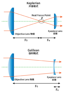
What are the available design types?
1. Keplerian: Consists of two positive lenses with a real focal point between them. This is suitable for applications requiring spatial filtering, but can easily cause air breakdown at high powers.
2. Galilean: Consists of a negative lens and a positive lens. It has no internal focal point, resulting in a more compact structure and is the most common type in industrial systems. *Beam Expanders: Keplerian & Galilean
04 Closed-loop servo system
This section will explain in depth how the scanning galvanometer achieves its exceptional speed and accuracy through a high-speed, high-precision closed-loop servo system.
1. Why is closed-loop control necessary?
An open-loop system simply issues commands without regard for the results. It has no sense of its actual position and is highly susceptible to drift, load variations, and environmental disturbances.
A closed-loop system uses feedback to continuously monitor and correct its output, and the performance of the galvanometer scanner depends entirely on this.
The basic operating mechanism of a closed-loop system is to continuously compare the commanded position (from the control software) with the actual position (from the galvanometer’s built-in position sensor). The difference between the two is called the position error. This error signal is the driving force of the entire control loop, and the goal is to drive this error to zero in real time.
2. From Digital Commands to Lens Deflection
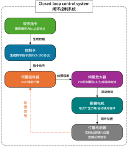
The signal flow for a complete control cycle is as follows:
1. Software Commands: The user-designed graphic in the software is interpreted as a series of (X,Y) target coordinates.
2. Control Card Processing: The control card (RTC board) receives these coordinates and generates digital command signals according to a specific communication protocol (such as XY2-100), which are then sent to the servo driver.
3. Error Calculation: The driver simultaneously receives the command signal from the control card and the feedback signal from the galvanometer position detector. An internal digital signal processor (DSP) or circuit compares the two and calculates the instantaneous position error.
4. Drive Current Generation: Based on the magnitude and direction of the position error, the servo amplifier uses a control algorithm (such as PID) to generate a precise drive current, which is applied to the galvanometer motor coil. When the error is large, a high current is generated, driving the motor quickly toward the target; when the error is small, the current is reduced accordingly, achieving smooth, precise positioning without overshoot.
5. Motor Deflection and New Feedback: This current generates torque, driving the lens rotation. Changes in the lens’ position are immediately detected by the position detector, generating a new feedback signal.
This “command → feedback → error calculation → drive” cycle repeats thousands or even tens of thousands of times per second, enabling dynamic and precise control of the lens’ position.
* Scanning galvanometer closed-loop control system
3. Position Detector
The position detector is the most critical sensor in a closed-loop servo system. Its performance directly determines the system’s ultimate accuracy, resolution, and stability.
Common Types:
Optical (analog): An infrared LED illuminates a shield fixed to the rotor shaft. As the rotor rotates, the shadow cast by the shield on the photodiode array changes accordingly. By measuring the differential current, the rotor angle can be accurately calculated.
Capacitive (analog): The angle is determined by measuring the capacitance value that changes with rotor rotation.
Digital Encoder (Grating): A high-resolution grating disk is fixed to the rotating shaft and read by an optical readhead. It directly outputs a digital angle signal, providing extremely high positioning accuracy, resolution, and very low long-term drift, and is commonly used in top-tier systems.
4. Servo Drive
The shift from analog to digital is the fundamental reason for the dramatic performance leap in modern galvanometer scanners.
Analog Control (Old Technology):
Disadvantages: Susceptible to electromagnetic interference and noise; cumbersome tuning, relying on manual adjustment of potentiometers, and component replacement often requires factory return; rigid control logic, lacking flexibility.
Digital Control (Modern Mainstream): Implementation: Control algorithms are executed in firmware using a high-speed digital signal processor (DSP).
Advantages:
1. Strong interference immunity: Digital communication protocols (such as XY2-100) are inherently insensitive to noise.
2. Advanced algorithms: Enable predictive control far more complex than PID. For example, model-based look-ahead control can eliminate tracking errors in advance.
What is the fundamental difference between analog and digital?
Analog servos are passive; they observe errors and react, always chasing the command, thus inevitably subject to tracking error. Digital servos, on the other hand, are active and predictive; they anticipate the path and plan ahead, thus achieving “zero tracking error” scanning. This also fundamentally solves key application problems such as corner overburning in additive manufacturing.
05 Key Performance Indicators
1. Speed Specifications
1. Marking/Writing Speed (Marking Speed): Typically measured in mm/s or characters/second (cps), this directly measures the application’s productivity.
2. Positioning/Jump Speed (Jump Speed): The speed at which the laser moves between two points when the laser is off. This determines the waiting time between processing steps.
3. Step Response Time (Step Response Time): The time required for the lens to move a specific angular step and stabilize within tolerance. This is a basic indicator of dynamic response capability; the shorter the time, the higher the throughput.
2. Accuracy Specifications
1. Accuracy: The degree of consistency between the actual position and the commanded position across the entire scanning field.
2. Repeatability: The ability to return to the same point multiple times from different directions. This is often more important than absolute accuracy.
3. Resolution: The smallest angular increment that the galvanometer can be commanded to move and resolve.
3. Stability Indicators
Thermal Drift: The slow change in position (zero point and gain) over time due to internal temperature fluctuations. It is a major source of error during long-term processing.
Jitter: The minute, high-frequency oscillation of the lens around the commanded position when stationary. High jitter degrades the quality and smoothness of the processed edge.
06 Control Architecture Challenges & Solutions
When we scale up a single galvanometer system to a complex application involving a large motion platform, the bottlenecks of traditional control architectures become apparent.
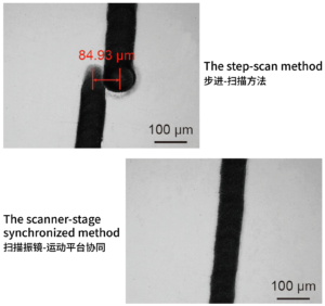
1. Traditional “Step-and-Scan” Mode
Inertial Constraints: The XY stage’s high inertia limits overall processing efficiency and dynamic response.
Field of View Limitations: The galvanometer’s scanning range is limited. For example, if it’s 100x100mm, to process a 500x500mm workpiece, the pattern must be cut into 25 pieces and processed one by one. This approach is prone to stitching errors at the joints.
Lack of Coordination: In traditional architectures, the stage and galvanometer are two independent systems. When a command is issued to the host computer, the stage first moves to position A. Once the stage stops, the galvanometer is then commanded to begin scanning. These two processes are simply executed sequentially.
Control Distortion: Delays and errors in traditional control loops can cause the actual laser trajectory to deviate from the designed pattern.
*Splicing error
2. Solution 1: Distortion Correction
To achieve micron-level accuracy, the inherent geometric distortion of the system must be corrected.
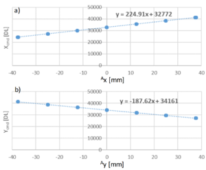
The traditional approach: Lookup Table (LUT). This involves measuring errors at thousands of points to create a compensation table, a tedious and time-consuming process, and its accuracy depends on point density.
The modern approach: Physical modeling based on sparse data. Only a small number of points, such as 5 x 5 = 25, are measured, and a comprehensive mathematical model describes the physical behavior of the entire system. Once the model is calibrated, the distortion at any point in the field of view can be accurately calculated.
*Lookup Table Calibration: Measured points are mapped to digital commands to determine the galvanometer calibration function.
3. Solution 2:
Infinite Field of View (IFOV) technology, also known as stage linkage or collaborative scanning, revolutionizes the “step-and-scan” model. It integrates the galvanometer and XY stage into a seamless, unified motion system through a unified intelligent controller.
How is unified motion achieved?
① Motion Vector Decomposition: The controller automatically analyzes your designed path and intelligently splits it into long, gentle motions (low-frequency components) that are handled by the stage. High-dynamic, complex details (high-frequency components, such as corners and small arcs) are handled by the galvanometer.
② Real-time Error Correction
Error-proofing (e.g., SCANLAB/ACS): Through forward-looking trajectory planning, an optimized path is pre-calculated that both systems can perfectly track.
Error Correction (e.g., Aerotech): Through real-time feedback, the galvanometer actively compensates for dynamic tracking errors introduced by the stage, ensuring absolute precision in the final position.
*Aerotech IFOV technology
4. Solution Three: Precision Synchronous Control
Even with the algorithm, high-fidelity actuators are needed to ensure the ultimate results.
① Direct Drive (PWM Direct Drive)
The traditional multi-layered process of controller → driver → motor introduces latency. Modern controllers bypass the intermediate driver, sending the lowest-level PWM control signals directly to the motor and receiving direct, high-speed position feedback from the motor. This significantly reduces latency and improves dynamic response.
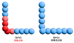
② Distance-Based Laser Triggering (Position Synchronous Output – PSO)
Traditional methods use time triggering, emitting a laser pulse at fixed intervals. The PSO method triggers based on spatial distance, for example, emitting a pulse every 5 microns of movement. Regardless of the system’s speed, the laser energy is evenly distributed along the path. This fundamentally ensures consistent processing energy and resolves the corner burn-in issue mentioned in the introduction.
*Comparison with and without PSO
③ Advanced Power Control
Using technologies such as power calibration mapping and analog vector tracking, the controller adjusts laser power in real time based on the beam position and velocity, ensuring constant energy density throughout the entire machining process.
The ultimate goal of all these technologies is to achieve process parameter invariance. For engineers, this means that the set process parameters, such as linear energy density and beam overlap, are the physical results ultimately achieved on the workpiece. This eliminates the need for trial and error, or repeated parameter adjustments to compensate for dynamic equipment imperfections.
Conclusion
The galvanometer scanner has evolved from a simple two-dimensional beam deflector to a multi-axis, sensor-rich, and highly integrated photonic processing subsystem.
In the past, it was a standalone actuator—a device encapsulating a motor and mirrors, whose core task was to deflect the beam based on input signals.
Now, it is an integrated functional unit. It physically integrates the Z-axis focusing module, has a built-in digital controller, and provides real-time operating status and performance metrics through diagnostic data streams.
So, what does the future hold? Will it be possible to achieve deep data interaction and collaborative operation with other motion devices, such as robots and motion platforms, to achieve true intelligent manufacturing?